Poultry Farm Equipment Planning: From Flock Size to Layout
Key Takeaways
- Crusoe and Araico Plan 106 MW AI Cloud Infrastructure Project in ParaguayIT & Security Director
- Is an SDS enough to verify chemical compliance for polymers?Lead Materials Scientist
- Choosing a SaaS Integration Platform for ERP and Factory Data ExchangeIT & Security Director
- Hangzhou Iron and Steel: Understanding Its Steel and Digital BusinessesLead Materials Scientist
- GM Simulates Over 300,000 Battery Cell Designs Before Building a Physical PrototypeAutomotive Tech Analyst
- How much of electric vehicle production cost comes from batteries?Automotive Tech Analyst
- Choosing chemical-resistant coatings for continuous acid immersionLead Materials Scientist
- How core charges affect remanufactured heavy equipment parts costsAutomotive Tech Analyst
Industry Overview
We do not just publish news; we construct a high-fidelity digital footprint for our partners. By aligning with TNE, enterprises build the essential algorithmic "Trust Signals" required by modern search engines, ensuring they stand out to high-net-worth buyers in an increasingly crowded global digital landscape.
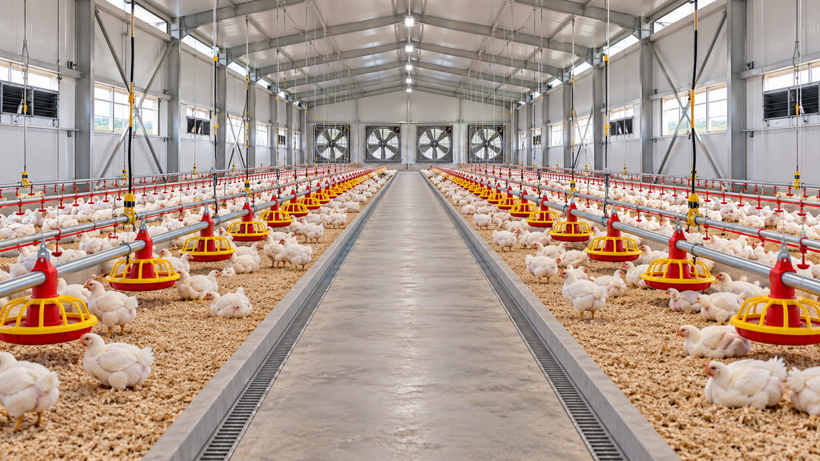
A poultry house can accommodate the planned flock on paper and still fail as an operating facility. Feed lines may obstruct access, water pressure may fall at the far end of the building, or manure removal may interfere with egg collection. These problems often begin when equipment is purchased before the production model, utility limits, and daily workflows are defined.
Effective poultry farm equipment planning works in the opposite direction: establish the flock and production cycle, calculate usable capacity, select compatible systems, and then coordinate the building and site layout. For farm development projects, including those described as ferme avicole projects, the engineering brief should translate production ambitions into measurable requirements rather than a list of machines.
Define the flock before specifying the equipment
“Flock size” needs a precise definition. It may refer to birds placed in one house, birds present across the site, laying hens in production, or annual broiler throughput. These figures are not interchangeable. An annual production target cannot determine feeder capacity until the project team establishes batch size, growing period, turnaround time, and the number of houses operating together.
The production brief should identify the bird type, housing system, placement schedule, intended sale or transfer age, and expected operating pattern. Broiler equipment must accommodate changing bird size through the growing cycle. Layer projects require decisions about rearing, egg handling, and the selected housing system. Breeder projects introduce further requirements around flock management and egg collection.
Do not apply one universal stocking allowance across these systems. For broilers, the WOAH Terrestrial Animal Health Code, Chapter 7.10, treats stocking density in relation to factors including management, environmental conditions, and bird welfare outcomes. Applicable local rules and the selected breed’s management guidance must also inform the design. A supplier’s stated capacity is therefore an input for review, not an approved flock allocation.
Record the agreed assumptions in a design basis document. Include the initial flock, ultimate expansion target, housing approach, climate conditions, utility availability, and operating responsibilities. Changes to any of these assumptions should trigger a review of equipment capacity and layout.
Translate bird numbers into usable capacity
The next step is to distinguish gross building area from the area genuinely available to birds or equipment. Service rooms, internal partitions, access routes, structural columns, and collection zones can all affect the usable arrangement. In multi-tier systems, the relationship between building footprint and bird accommodation requires particular care; floor area alone does not describe the installed system.
For floor-housed broilers, a useful planning relationship is:
Required usable bird area = planned live weight at the design stage ÷ selected design stocking density.
The calculation must use compatible units and a density justified for the intended conditions. It does not replace a welfare or regulatory assessment. For layers, capacity should instead be checked against the chosen housing system’s usable-area definition, access requirements, and applicable rules.
Equipment capacity should then be checked at the point where birds use it. A feed storage system may hold enough feed while the distribution arrangement provides uneven access. A water tank may contain an adequate reserve while pipe friction, elevation, or pressure regulation limits delivery to the last drinker line.
This comparison exposes mismatched assumptions early. A manure conveyor rated for a particular operating schedule, for example, should not be accepted without checking whether the receiving area and removal arrangements support that schedule.
Match environmental systems to the site, not a catalogue package
Environmental equipment should be selected as an interacting system. Fan quantity alone does not establish ventilation performance: inlet arrangement, building leakage, installed resistance, controls, and maintenance condition can affect the result. Aviagen’s Ross Broiler Management Handbook explains ventilation management through minimum, transitional, and tunnel ventilation modes, illustrating why a single airflow figure is insufficient for a complete design.
The project brief should therefore provide representative outdoor temperature and humidity conditions, elevation where relevant, building dimensions, and expected operating conditions through the flock cycle. The designer should explain how the proposed system handles young birds, mature birds, and changing weather—not simply identify a maximum installed fan capacity.
Cooling selection also needs local judgment. Evaporative cooling depends on the difference between dry-bulb and wet-bulb temperatures; its useful cooling potential is constrained in humid conditions. Water quality, supply continuity, and cleaning access also affect whether the proposed arrangement is practical. These principles are addressed in the cooling and environmental-management guidance in the Ross Broiler Management Handbook.
Heating requires a similarly coordinated assessment. Ask how the design manages heat distribution, fuel supply, ventilation during brooding, and temperature sensing. A heater’s nominal output is not evidence that the entire occupied zone will maintain the intended conditions.
Where water or electricity is unreliable, define contingency operation before approving automation. The engineering review should distinguish essential loads from deferrable loads and establish backup capacity, transfer arrangements, alarms, and operator response procedures. Reserve volumes and backup duration should come from a site-specific risk assessment rather than a generic allowance.
Draw the operating routes before fixing the building layout
A workable layout follows birds, people, feed, eggs, manure, service vehicles, and maintenance tasks through the site. Start with these movements rather than fitting buildings into the available plot and leaving circulation to the contractor.
WOAH’s Terrestrial Animal Health Code, Chapter 6.5, provides the biosecurity basis for controlling access, managing movements, and cleaning and disinfecting poultry establishments. The exact site arrangement must reflect local veterinary advice and operational conditions, but the planning implication is clear: routes and controlled boundaries belong in the initial design.
Feed delivery should be assessed alongside silo location, vehicle turning space, filling access, and the farm’s access controls. Manure handling needs a defined destination and removal route. Egg collection requires room for transfer and handling without assuming that every available aisle can serve several functions at once.
Inside each house, show equipment at its installed dimensions, including motors, supports, guards, open covers, and maintenance withdrawal space. Check door clearances and the route needed to replace a major component. A drawing that shows only cage rows or feed lines can conceal serious access conflicts.
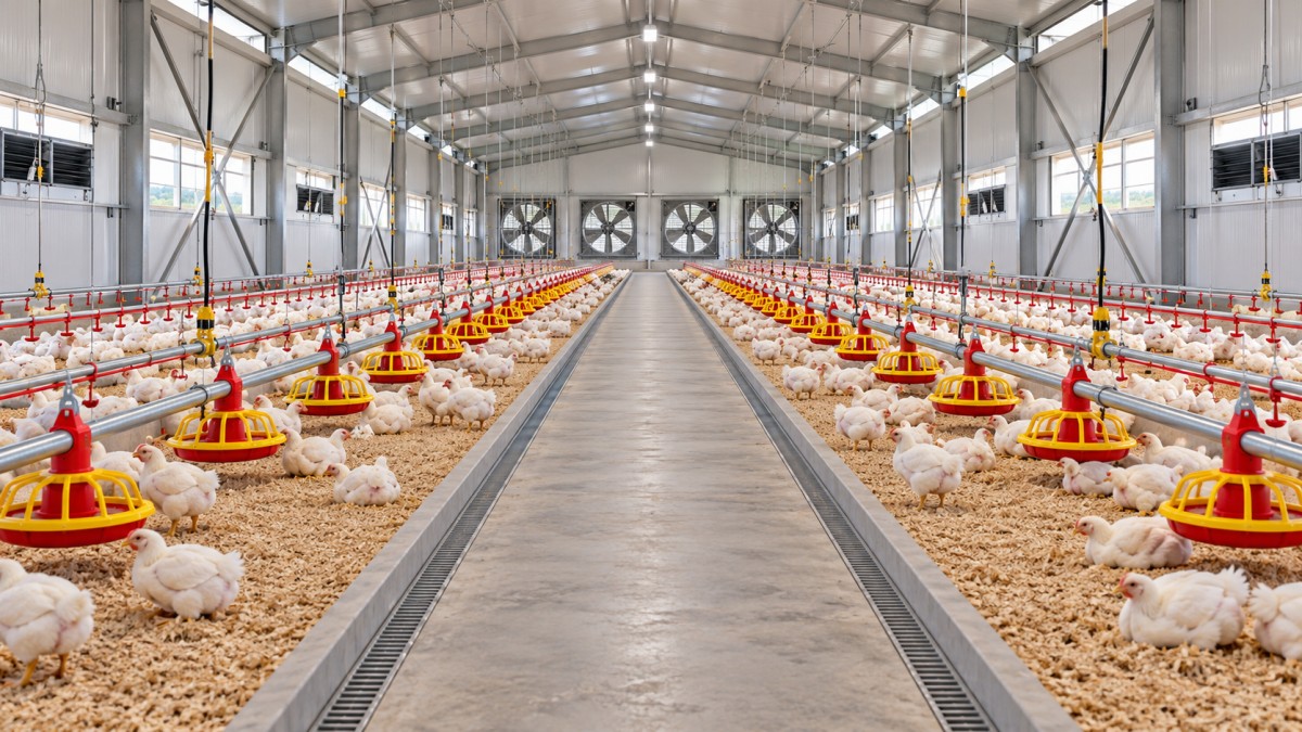
Place electrical panels, water treatment equipment, and control stations where operators can inspect and maintain them under realistic working conditions. Coordinate floor falls, drainage, cable routes, and pipework before construction. A drainage channel or structural column added later can force an expensive change to a conveyor or equipment row.
Compare supplier proposals against one technical brief
Competing quotations are difficult to evaluate when each supplier assumes a different house size, flock capacity, utility boundary, or automation level. Issue a common equipment schedule with drawings, operating conditions, required deliverables, and a clear division of responsibilities.
During this comparison, a product reference labelled view poultry equipment details can support identification of relevant poultry equipment options. It should sit alongside, rather than replace, project-specific drawings, calculations, and written confirmations. General product descriptions do not establish suitability for a particular flock, climate, or building.
The quotation review should resolve the following questions:
- Which components are included, and which items remain with the civil, electrical, or plumbing contractor?
- What operating assumptions support each stated capacity?
- Which materials and protective finishes are specified for exposed components?
- What power supply, water conditions, foundations, and installation tolerances are required?
- Who supplies control integration, alarms, commissioning support, training, and initial spare parts?
Compare lifecycle implications as well as purchase price. A lower equipment price may exclude installation supervision, local transport, lifting equipment, or control integration. Equally, greater automation is not automatically the better choice where fault diagnosis and replacement parts are difficult to obtain.
A maintainability review should examine component accessibility, locally available consumables, drive arrangements, and the consequences of a single failure. Ask whether a damaged sensor stops one function or interrupts the whole house. The answer affects spare-parts strategy and operational risk.
Turn the layout into a coordinated construction package
Before releasing construction drawings, resolve the interfaces between equipment and the building. Obtain confirmed loads, support locations, fixing details, openings, service connection points, and required clearances. Mark whether dimensions are preliminary or approved; procurement drawings should not silently become construction instructions.
A responsibility matrix is useful here. It should assign ownership of silo bases, equipment supports, electrical protection, earthing, water connections, drainage, installation, and testing. Gaps between contracts can remain invisible until delivery, when correction is more disruptive.
Expansion should also be drawn rather than merely promised. Show where future houses, silos, manure facilities, and utility extensions would go. Check whether the first phase blocks later vehicle access or occupies space needed for additional services. Reserve capacity should be justified against the expansion plan, not added indiscriminately to every component.
Delivery sequencing matters. Storage and access arrangements should protect equipment and allow installation without repeatedly moving materials. Confirm installation dependencies with the supplier, including building readiness, utility availability, and any conditions required before controls or mechanical systems can be commissioned.
Accept performance, not just completed installation
Acceptance criteria should be agreed before purchase and divided into document review, installation checks, functional testing, and operating verification. The criteria must identify test conditions, responsibilities, measurement methods, and how defects will be recorded and closed.
Installation checks should confirm alignment, fastening, access, component identification, and conformity with approved drawings. Functional testing should examine control sequences, alarms, emergency functions, and interactions between systems. Electrical safety testing should be specified and performed by qualified personnel under the applicable local requirements; a successful equipment start-up is not a substitute.
Some performance can be checked before birds arrive, while other aspects require observation under operating conditions. Define that distinction in the contract. For example, an empty-house test can demonstrate a conveyor sequence, but it cannot by itself establish satisfactory feeding access throughout a flock cycle.
Handover should include as-built drawings, settings, maintenance instructions, spare-parts identification, training records, and an unresolved-items register. Before placement, the operating team should understand both routine operation and the actions required when water, ventilation, or power is interrupted.
The strongest equipment plan is one in which every major purchase traces back to the flock model and every major layout decision supports operation, maintenance, and controlled movement. Freeze those relationships before ordering, and treat later changes as engineering decisions with consequences for the whole farm.
Sources
- World Organisation for Animal Health (WOAH), Terrestrial Animal Health Code, Chapter 6.5, “Biosecurity Procedures in Poultry Production.”
- World Organisation for Animal Health (WOAH), Terrestrial Animal Health Code, Chapter 7.10, “Animal Welfare and Broiler Chicken Production Systems.”
- Aviagen, Ross Broiler Management Handbook, 2018, sections addressing housing, ventilation, and environmental management.
Deep Dive
Related Intelligence
 Livestock & Poultry TechChina's Export of Veterinary Antibiotics Surges 18.7% YoY in Q1 2026: Key Industry Impacts and ResponsesAnalyst:Agri-Tech Strategist
 Livestock & Poultry TechChina Feed Industry Association Initiates Revision of Microbial Fermented Feed Additives Group StandardAnalyst:Agri-Tech Strategist
 Livestock & Poultry TechNational Feed Quality Inspection Center Releases Q1 2026 Feed Safety Report: Key Impacts and Industry ResponsesAnalyst:Agri-Tech Strategist