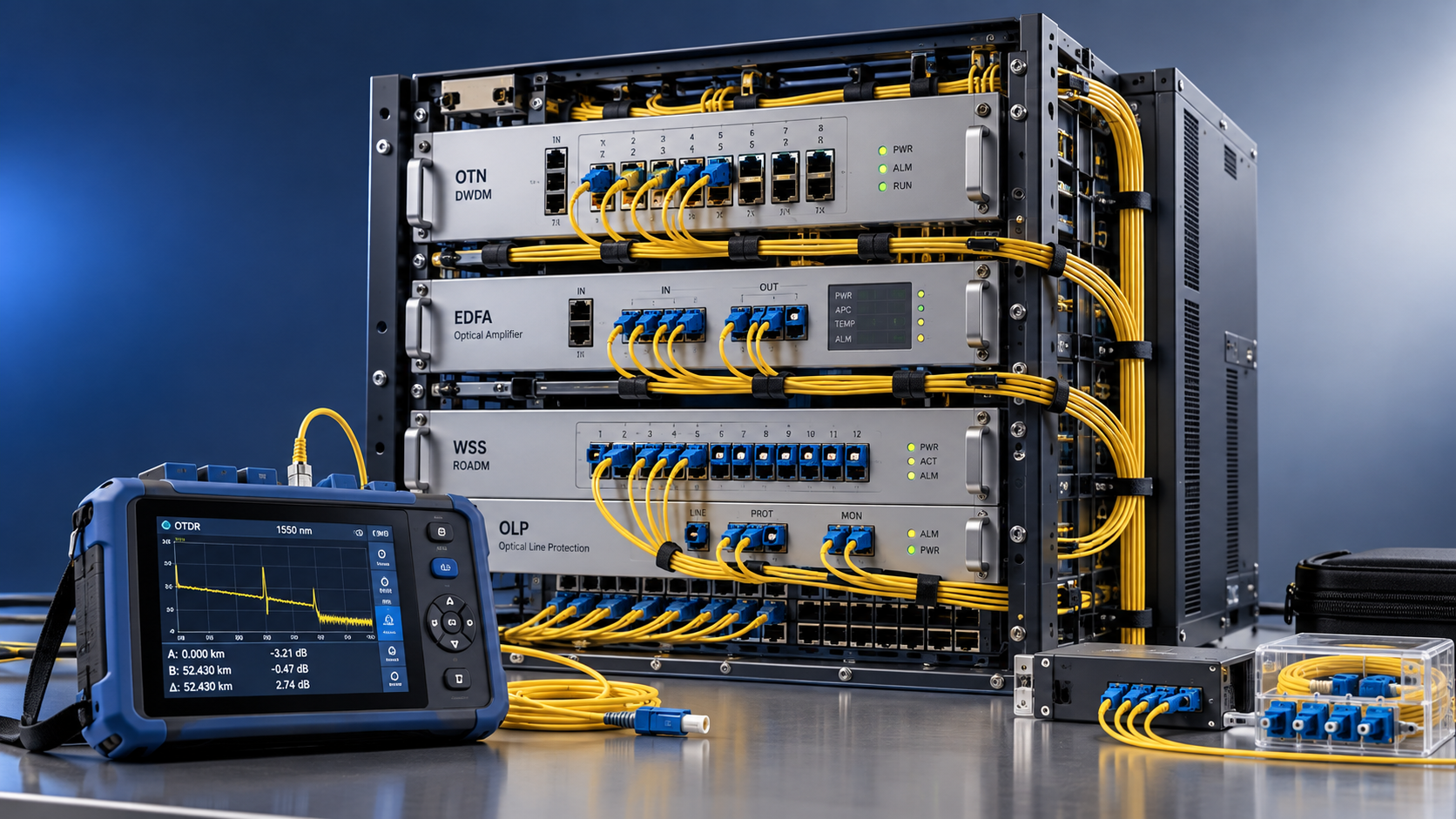
Choose fiber optic equipment for telecommunications by validating performance across your actual route, planned wavelength loading, and operating conditions before comparing headline transmission rates.
For technical evaluators, the decisive question is whether each channel retains adequate optical margin through the complete system, including amplifiers, ROADMs, repairs, and future expansion.
A platform that meets initial specifications can still restrict wavelength growth, increase regeneration costs, or create interoperability problems that undermine its apparent purchase savings.
This guide explains how to characterize routes, assess coherent transmission, validate supplier claims, and compare lifecycle costs using measurable engineering criteria and practical acceptance tests.
Start with the route: what must the equipment actually support?
Build a route specification before requesting equipment proposals. Distance alone cannot describe a long-haul link because span losses, fiber properties, and intermediate nodes vary considerably.
Document each span’s length, measured attenuation, splice history, connector losses, fiber type, and available amplifier locations. Include power availability, environmental conditions, and site access constraints.
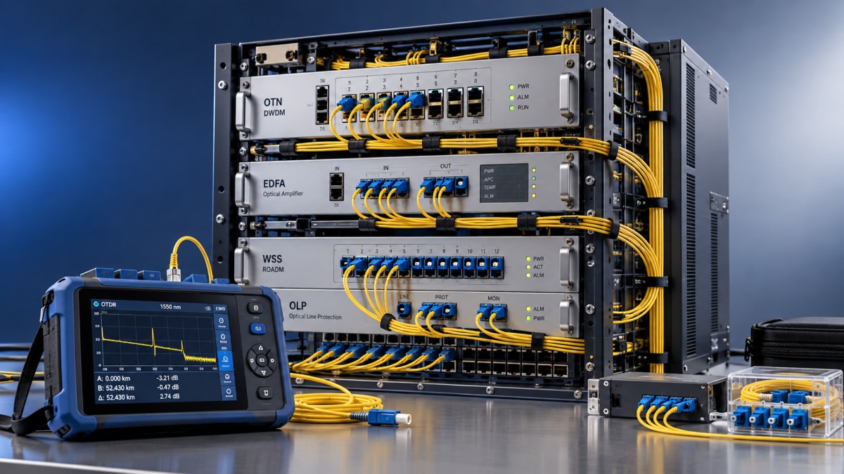
Use optical time-domain reflectometer measurements to locate loss events, supported by calibrated insertion-loss measurements. Record test wavelengths and methods so vendors receive comparable route data.
Identify fiber characteristics from installation records and measurements where necessary. Chromatic dispersion, polarization-mode dispersion, and effective area influence achievable performance, especially on older mixed-fiber routes.
Define service requirements separately: initial capacity, expected growth, client interfaces, latency limits, availability targets, and restoration behavior. Distinguish requirements for working routes and protection routes.
Specify the optical architecture, including point-to-point sections, express paths, and reconfigurable optical add-drop multiplexers, or ROADMs. Each additional filtering stage can change feasible transmission modes.
For every supplier, provide the same route assumptions and growth scenario. Otherwise, differences in proposed capacity may reflect inconsistent modeling rather than better equipment performance.
Evaluate optical margin, not advertised reach
A transceiver’s advertised reach is conditional. It depends on fiber characteristics, amplification, channel loading, filtering, modulation, error correction, and the performance threshold used during qualification.
Separate span power feasibility from end-to-end signal quality. An amplifier may restore optical power while adding noise that reduces the receiver’s ability to recover data.
For an illustrative span, 80 kilometers at 0.22 dB per kilometer produces 17.6 dB fiber attenuation. Connectors, splices, and passive components add further loss.
If those additional losses total 2 dB, the span reaches 19.6 dB before engineering allowance. These illustrative values are planning inputs, not universal design targets.
Require suppliers to demonstrate amplifier input levels, output levels, gain range, and saturation behavior for every span. Check both initial loading and planned maximum loading.
Then evaluate optical signal-to-noise ratio, or OSNR, alongside nonlinear propagation penalties. Higher launch power can improve noise tolerance initially, but eventually increases nonlinear distortion.
Ask whether reported margin means measured OSNR above a receiver threshold or modeled generalized SNR including nonlinear noise. These quantities require different interpretations and assumptions.
Require explicit allowances for aging, repair splices, measurement uncertainty, and operating variation. Agree on margin definitions and reference bandwidths before treating vendor figures as comparable.
Which coherent transmission mode delivers useful capacity?
Coherent transmission uses digital signal processing to compensate for substantial chromatic dispersion and track polarization effects. Compensation capability remains finite and must match the route.
Ask for supported chromatic-dispersion and polarization-mode-dispersion limits at each proposed operating mode. Legacy dispersion-compensation modules may add unnecessary loss and nonlinearity in coherent designs.
Evaluate their removal through route engineering rather than assuming either retention or removal is always correct. Mixed-generation systems may introduce constraints that require additional investigation.
Compare transceivers by delivered capacity per wavelength at the required margin. A higher nominal rate has limited value if the route forces a lower operating mode.
Modulation, baud rate, probabilistic shaping, and forward error correction jointly determine capacity and reach. Request mode-specific thresholds, spectral requirements, and power consumption from each supplier.
Higher-order modulation generally requires better signal quality. Higher baud rates can improve wavelength capacity but require adequate passbands throughout multiplexers, wavelength-selective switches, and ROADM paths.
For example, compare a higher-capacity mode requiring regeneration against a lower-capacity mode operating transparently. Include extra wavelengths, regeneration sites, electrical power, and maintenance costs.
Check client mapping and usable payload as well. Headline line rates, Ethernet service capacity, and transport overhead are different quantities that can distort commercial comparisons.
Choose amplification and ROADMs as one optical system
Erbium-doped fiber amplifiers are common in long-haul systems, but selection requires more than matching gain to span loss. Noise figure and output capability also matter.
Verify performance across the intended wavelength band and loading range. Gain flatness, automatic gain control, and channel add/drop transients can affect services during routine operations.
Distributed Raman amplification can improve signal quality on challenging spans, potentially extending transparent reach. Its value depends on fiber conditions, operational complexity, and site constraints.
Request a quantified comparison against conventional amplification, including avoided regeneration and additional maintenance requirements. Require appropriate connector management and laser-safety procedures wherever Raman pumping is proposed.
For ROADMs, compare degree count, add/drop capacity, supported spectrum, and passband behavior. Repeated filtering can impair wide signals even when total optical power appears satisfactory.
Model the longest operational path and the expected restoration path. A service may traverse additional ROADMs after a failure, reducing the margin available during recovery.
For future band expansion, confirm compatible amplifiers, filters, monitoring, and fiber behavior. Supporting additional spectrum requires system-level qualification rather than an assumption of straightforward upgrades.
Will components from different suppliers actually work together?
Separate client-interface compatibility, coherent line-interface interoperability, and management integration. Success in one area does not establish compatibility across the rest of the transport system.
A standardized pluggable form factor establishes mechanical and electrical characteristics, but does not guarantee coherent interoperability. Modulation, framing, error correction, and supported operating profiles must align.
Where suppliers claim standards-based interoperability, request the exact specification, revision, operating mode, and demonstrated equipment combinations. Treat proprietary extended-reach modes as separate qualification cases.
In an open line system, confirm who controls wavelength provisioning, launch power, spectrum allocation, and fault diagnosis. Ambiguous responsibilities can lengthen outages despite technically compatible hardware.
Check host-platform support for coherent pluggables, including thermal limits, power budgets, firmware, diagnostics, and licensing. A supported cage alone does not establish operational readiness.
Require a practical integration demonstration covering service creation, alarm reporting, performance telemetry, and software upgrades. Verify that exported metrics retain consistent definitions across management tools.
Document support ownership before purchasing. When a wavelength degrades, the agreement should identify who investigates the terminal, optical line system, fiber plant, and combined performance.
Turn vendor claims into measurable acceptance criteria
Use a compliance matrix that ties every important requirement to evidence and a pass condition. Mark unverified claims clearly rather than treating proposal language as proof.
Request design files or sufficiently detailed reports to audit assumptions. A single screenshot showing positive margin cannot explain loading, filtering penalties, or excluded operating conditions.
During laboratory qualification, reproduce representative attenuation, filtering, and loading conditions. Variable attenuation alone cannot reproduce accumulated amplifier noise, nonlinear propagation, or every field impairment accurately.
Agree which impairments laboratory tests reproduce and which require field validation. This prevents an apparently successful bench demonstration from becoming unsupported evidence for route-wide performance.
Monitor pre-FEC error metrics, corrected errors, uncorrectable events, received power, and available quality indicators. Normalize terminology because vendors may report different metrics under similar names.
Define observation periods and traffic conditions before testing begins. Zero post-FEC errors during a brief demonstration does not establish adequate margin for long-term operation.
Include channel additions, amplifier changes, fiber interruptions, and protection switching where applicable. Acceptance should demonstrate both steady-state performance and the system’s response to operational events.
Compare lifecycle cost at the same delivered service level
Compare fiber optic equipment for telecommunications using equivalent capacity, availability, route assumptions, and expansion timing. Purchase price alone rarely captures the cost of long-haul operation.
Include terminals, amplifiers, ROADMs, regeneration, software licenses, support, power, cooling, rack space, spares, and field labor. Account for leased facilities where equipment placement requires them.
Evaluate energy consumption at the operating mode you expect to deploy. Maximum-throughput efficiency figures may misrepresent a link running a more robust, lower-capacity transmission mode.
Calculate cost per delivered gigabit using usable service capacity and a consistent evaluation period. Include staged purchases so unused future capacity does not appear financially free.
Stress-test the comparison against slower demand growth, higher site costs, and additional regeneration. A credible recommendation should explain which assumptions could change the preferred option.
Check expansion licenses, spectrum limits, spare-part availability, software support periods, and component replacement policies. These details can determine whether future growth requires incremental spending or redesign.
Use mandatory technical gates before weighted scoring. Equipment that fails required route margin, restoration behavior, or support obligations should not win through lower upfront pricing.
Make the final decision around verified operating margin
The strongest choice combines measured route data, realistic capacity forecasts, transparent optical modeling, and acceptance results. No individual transceiver specification can substitute for that evidence.
Shortlist systems that satisfy service requirements with documented margin under expected loading and protection conditions. Then compare expansion flexibility, operational integration, and lifecycle cost.
Before signing, attach the agreed route assumptions, operating modes, acceptance thresholds, and support responsibilities to the commercial package. This makes the promised outcome reviewable and enforceable.
A well-selected long-haul platform delivers useful capacity today while preserving practical growth options. Its value rests on repeatable field performance and manageable operating costs.