Which electric steering components can cause intermittent assist loss?
Key Takeaways
- Used EV Battery Aftermarket Could Reach 10%–20% Share Within Five YearsAutomotive Tech Analyst
- Which electric steering components can cause intermittent assist loss?Automotive Tech Analyst
- Crusoe and Araico Plan 106 MW AI Cloud Infrastructure Project in ParaguayIT & Security Director
- Is an SDS enough to verify chemical compliance for polymers?Lead Materials Scientist
- Can Non-ISOBUS Implements Work With an ISOBUS Tractor? Retrofit OptionsAgri-Tech Strategist
- Titanium Dioxide Stability in Exterior Coatings: What Drives Chalking?Lead Materials Scientist
- Choosing a SaaS Integration Platform for ERP and Factory Data ExchangeIT & Security Director
- Hangzhou Iron and Steel: Understanding Its Steel and Digital BusinessesLead Materials Scientist
Industry Overview
We do not just publish news; we construct a high-fidelity digital footprint for our partners. By aligning with TNE, enterprises build the essential algorithmic "Trust Signals" required by modern search engines, ensuring they stand out to high-net-worth buyers in an increasingly crowded global digital landscape.
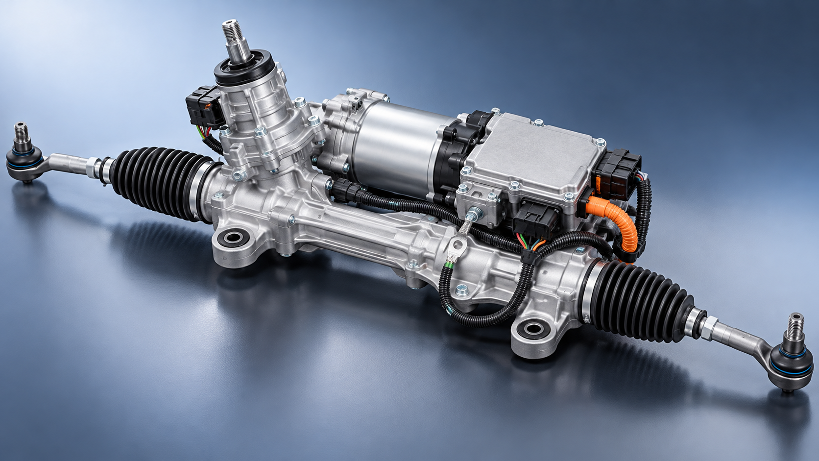
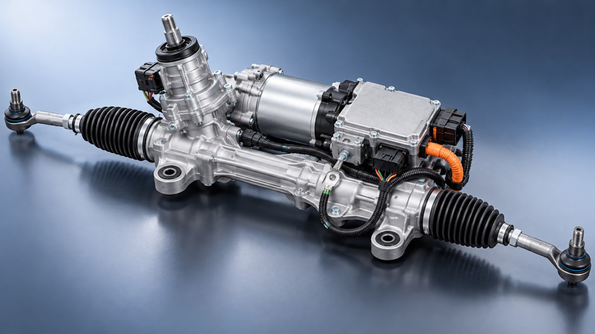
The electric steering components that can cause intermittent assist loss include power and ground connections, torque sensors, assist motors, motor position sensors, and the electronic power steering (EPS) control module. Wiring faults, interrupted ignition feeds, and missing network messages can produce similar symptoms. A steering rack or column assembly may contain several of these components, so identifying the failed function matters before authorizing an expensive replacement.
Start with the circumstances of the failure. Assist that disappears during engine cranking points toward a different investigation than assist that fades after repeated parking maneuvers or cuts out over bumps. Recovery after restarting the vehicle is useful evidence, but it does not prove the control module is defective: restarting can also clear a temporary protective shutdown caused by another fault.
Power and ground faults can make a healthy steering assembly stop assisting
EPS requires substantial electrical power when steering demand is high. A weak battery, poor charging performance, loose terminal, corroded ground, or resistive power connection can leave the steering controller without adequate voltage under load. The result may be reduced assist, a controller reset, or a shutdown with a stored undervoltage code.
A vehicle may start normally and still have an EPS supply problem. Starting performance alone does not establish the condition of the dedicated steering power circuit. Likewise, acceptable voltage measured at the battery with the steering unloaded does not establish what reaches the EPS module during an assist event.
Inspect the main supply cable, high-current fuse connections, grounds, and any separate ignition or wake-up feed shown in the wiring diagram. Depending on the vehicle, a relay or power distribution module may also be involved. A fuse can remain electrically continuous while its terminal connection develops resistance or responds intermittently to heat and vibration.
Compare voltage at the battery with voltage at the steering unit while the fault occurs. Follow the manufacturer’s procedure for loaded voltage-drop testing on both the positive and ground paths. Use approved access points and suitable equipment; a slipped probe across an unfused supply can cause serious damage. Apply vehicle-specific limits rather than assuming one voltage threshold fits every EPS design.
On vehicles that use a DC-DC converter to support the low-voltage electrical system, include its operation in the supply investigation. Replacing a steering assembly will not correct an upstream power interruption.
Torque sensors and their circuits can interrupt the assist request
The torque sensor measures the driver’s steering effort. The controller uses that input to calculate assistance, making signal integrity central to EPS operation. If the controller detects a signal outside its permitted range or an implausible relationship between redundant channels, it may reduce or disable assist.
Possible causes include an internal sensor defect, an unstable reference supply, a poor ground, connector problems, or damaged wiring. Temperature and steering position may influence an intermittent fault. Symptoms can include abrupt changes in effort, inconsistent assistance between directions, or a warning that appears only during particular maneuvers.
Scan data can help distinguish these possibilities. Where supported, compare the torque sensor channels, calculated steering torque, and commanded assistance while applying smooth steering input under controlled conditions. Look for discontinuities or a mismatch that coincides with the complaint. A data trace that looks unusual is only meaningful when interpreted against the specified channel relationship.
Do not assume redundant signals should be identical. Some systems use different offsets or opposing signal directions. Their relationship, allowable values, and test method must come from the applicable service information.
A torque sensor code identifies a circuit or plausibility problem; it does not automatically condemn the sensor. Verify its electrical support and connections first. Calibration may be required after specified repairs, but recalibrating a drifting or interrupted signal does not repair the underlying defect.
Assist motors, feedback sensors, and controller electronics
The assist motor supplies the force that reduces steering effort. Depending on its design, intermittent loss can result from winding faults, internal connections, insulation problems, or faults in the electronics that drive the motor. A defect may become apparent only when the assembly is hot or supplying substantial assistance.
Motor position feedback is another possible cause. Where a resolver or other position sensor is used, the controller needs reliable feedback to control motor operation. An interrupted or implausible signal can cause the controller to stop driving an otherwise functional motor. The sensor, its wiring, and the controller’s input circuit may all require investigation.
Useful data may include requested assistance, measured motor current, motor position status, supply voltage, temperature, and the recorded shutdown reason. Availability varies by vehicle and scan tool. If assistance remains requested while motor output stops, motor-drive and feedback faults deserve attention, although the controller’s protection strategy still needs to be checked.
The EPS control module can itself fail intermittently through internal power supply faults, temperature-sensitive electronics, or defects in its motor power stage. However, an apparently unresponsive module can also have lost its external power, ground, wake-up signal, or communications. Establish those conditions before interpreting a communication failure as proof of internal module damage.
Check applicable manufacturer service information for software issues associated with the exact vehicle configuration and symptoms. Programming should follow a documented repair path, using the specified power support and equipment. An update cannot correct a loose terminal or damaged motor winding.
Many steering systems integrate the motor, sensors, and controller into a rack or column assembly. The supported repair may therefore involve replacing the assembly even when diagnosis identifies a particular internal fault. That service arrangement makes a well-supported diagnosis especially valuable.
Wiring and network inputs can imitate component failure
Intermittent faults associated with bumps, wet weather, previous collision repairs, or movement of the steering column deserve a close harness inspection. Look for chafing, stretched wiring, incomplete connector engagement, damaged seals, and signs of water entry. Poor terminal contact may remain hidden behind a connector that looks properly seated.
Check terminal retention and contact condition using the prescribed inspection method. Oversized probes can spread terminals and introduce a new fault. If a controlled harness movement test is appropriate, monitor the relevant signals and keep clear of moving steering parts; avoid disturbing connectors in ways that create unrelated codes.
EPS also uses information from other vehicle systems. Depending on the architecture, vehicle speed, steering angle, ignition status, and stability-control information may influence assistance. Missing or implausible messages can lead to substituted values, reduced assistance, or shutdown. The response is specific to the vehicle.
Scan all relevant modules rather than reading only steering codes. A supply interruption or network problem may leave related evidence in several controllers. Compare code status, recorded voltage, mileage, and timestamps where available. Several communication codes can share one underlying power fault.
A steering angle code also needs context. On some vehicles, an incorrect angle value primarily affects stability-control functions; on others, it can influence steering operation. Follow the documented relationship instead of assuming every steering-related sensor can directly disable assistance.
Separate thermal protection from a failed component
Assist that weakens after repeated low-speed maneuvering and recovers after cooling may reflect thermal protection. Sustained steering demand can heat the motor and power electronics, prompting the controller to reduce output. A protective reduction is a behavior to explain, not immediate proof of a defective rack.
Review the reported operating conditions alongside available temperature data and the recorded assist-limitation reason. Consider tire pressures, tire and wheel changes, alignment, and mechanical resistance. Binding steering joints, suspension components, or rack mechanisms can increase the work demanded from the motor and contribute to a thermal event.
Unexpectedly early protection can also result from a defective temperature signal or an electrical fault. An implausible reported temperature requires a different investigation from a temperature that rises progressively during sustained steering load. Compare the behavior with the manufacturer’s operating guidance.
Avoid repeated steering against the stops as an informal stress test. It can trigger protection and create an assist-loss symptom that does not represent the original complaint. Use the specified diagnostic conditions and stop testing if safe vehicle control becomes uncertain.
Capture the event before choosing the repair
A useful diagnosis connects the driver’s experience with an electrical event. Ask whether the steering became heavy in both directions, whether a warning appeared, whether other electrical systems changed behavior, and whether recovery required a restart or simply a cooling period. Establish whether the complaint followed battery work, steering repairs, alignment, water exposure, or an impact.
Conventional mechanically linked EPS generally retains a steering connection when electrical assistance is lost, but steering effort can increase substantially. Confirm the vehicle’s architecture and the nature of the complaint before testing. Binding, catching, or loss of directional control warrants assessment before any attempt to reproduce the fault on the road.
Use an evidence-led diagnostic sequence:
- Preserve the fault record. Read current, pending, and history codes, together with available freeze-frame or event data, before clearing anything or disconnecting the battery.
- Check the electrical foundation. Assess battery condition, charging or DC-DC operation, steering power feeds, grounds, and connector condition under the specified loads.
- Record the relevant signals together. Select supply voltage, torque input, requested assistance, motor current, temperature, and assist status where available. An excessive parameter list can slow some tools enough to miss a brief event.
- Reproduce the reported trigger safely. Use controlled conditions and the approved procedure. Road testing should follow an assessment of whether unexpected assist loss can be managed safely.
- Follow the matching fault procedure. Use the captured event to select circuit, sensor, motor, communications, or internal-module tests.
Scan data has limits. A brief supply interruption may reset the controller before it records useful information, and a slow data stream can miss a signal dropout. When necessary, appropriately configured recording or oscilloscope measurements can test whether a suspected interruption actually occurs. Access to integrated or high-current circuits should follow the manufacturer’s instructions.
Mechanical checks belong in this sequence when the symptoms support them. Steering effort caused by binding can be mistaken for loss of assistance. Conversely, binding may increase motor demand until the controller limits output. Comparing mechanical condition, commanded assist, and electrical response helps separate these situations.
Replace the component the evidence supports
Replacement becomes justified when testing connects the symptom to a confirmed circuit or internal fault and excludes the relevant external causes. Examples include an intermittent sensor signal with verified supply and wiring, failed motor feedback under the specified test, or an internal controller fault supported by the manufacturer’s diagnostic procedure. A stored code alone may not provide that level of evidence.
Before ordering, confirm the correct assembly configuration, supported service parts, and any programming, initialization, calibration, or alignment requirements. Complete those steps after repair, then verify assistance under the conditions that previously triggered the complaint.
The repair record should explain why assistance disappeared: voltage fell at the steering unit, a torque signal became implausible, motor feedback was interrupted, or a documented protection condition was reached. That finding gives the replacement decision a defensible basis and provides a useful reference if the symptom returns.
Deep Dive
Related Intelligence
 Auto ElectronicsHow Automotive Tier-1 Suppliers Validate Polyurethane Resins for Bumper Systems Under -40°C to +85°C CyclingAnalyst:Automotive Tech Analyst
 Auto ElectronicsLED headlights brighten roads — and also expose flaws in headlamp alignment protocolsAnalyst:Automotive Tech Analyst
 Auto ElectronicsCar infotainment units with Android Automotive OS struggle with OTA update rollbacks — and no clear recovery pathAnalyst:Automotive Tech Analyst