Layer Cage Capacity Planning: Cage Footprint vs. Poultry House Space
Key Takeaways
- How to analyze cybersecurity controls for regulatory complianceIT & Security Director
- How Do You Fix Missing Material Specs in a BIM Handover Model?Chief Civil Engineer
- SpaceX Completes $40 Billion Debt Financing for GPU PurchasesIT & Security Director
- How to identify supplier risks with supply chain cybersecurity analysisIT & Security Director
- Palo Alto Networks Confirms PHP2Shell RCE Flaws Affect PAN-OSIT & Security Director
- How much does cold weather reduce the range of electric scooters?Automotive Tech Analyst
- Used EV Battery Aftermarket Could Reach 10%–20% Share Within Five YearsAutomotive Tech Analyst
- Which electric steering components can cause intermittent assist loss?Automotive Tech Analyst
Industry Overview
We do not just publish news; we construct a high-fidelity digital footprint for our partners. By aligning with TNE, enterprises build the essential algorithmic "Trust Signals" required by modern search engines, ensuring they stand out to high-net-worth buyers in an increasingly crowded global digital landscape.
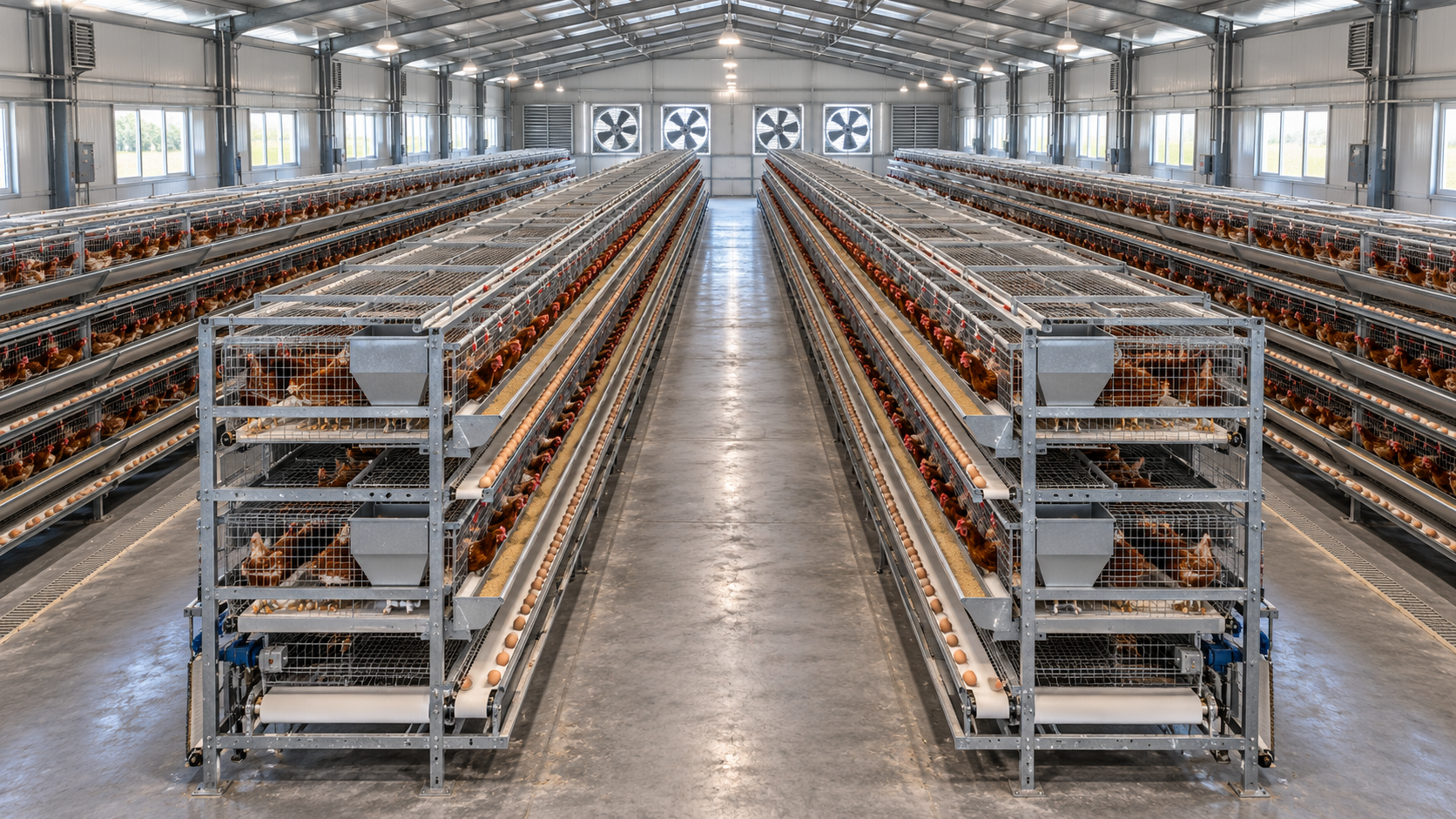
A layer cage can fit inside a poultry house without the proposed flock fitting the operating system. The difference is the space needed around the cages: inspection aisles, egg conveyors, manure discharge, feed equipment, ventilation components, maintenance access and exit routes. Capacity planning must account for those spaces before a project team commits to a building size or bird number.
The practical distinction is between cage footprint, which describes equipment occupying the floor, and poultry house space, which must support the complete installation and its daily operation. Dividing building floor area by cage footprint does not establish a defensible capacity. A workable plan connects compartment-level bird allowance, equipment geometry, building constraints and utility performance.
Establish what each dimension actually measures
Supplier drawings may describe a compartment, a cage section, a complete row or an installed assembly. These are different measurement boundaries. Before comparing quotations, project managers should require every dimension to identify its start and end points.
A procurement file described as chicken layer cage dimensions pdf in meters can provide a useful starting reference for dimensional review. However, a general dimensions-and-capacity guide is not a substitute for a project-specific installation drawing. The approved package should identify the selected configuration, measurement units, drawing revision and equipment included in the stated footprint.
Keep building dimensions and equipment envelopes in meters, while retaining any original millimeter dimensions needed for fabrication checks. Unit conversion should not erase precision. An outline rounded for preliminary budgeting may be unsuitable for locating anchors or checking a tight clearance.
Resolve housing requirements before calculating bird numbers
“Battery cage” is not a sufficient specification for regulatory review. Conventional and enriched cage systems have different implications, and some destinations or purchasing programs may require cage-free production. Establish the intended housing system and the destination market before treating a supplier’s stated bird capacity as an acceptable project target.
For example, European Union Council Directive 1999/74/EC distinguishes unenriched cages from enriched cages, prohibits keeping laying hens in unenriched cages from 1 January 2012, and specifies requirements for enriched systems. Those provisions should not be transferred automatically to projects in other jurisdictions. Source: Council Directive 1999/74/EC, Articles 5 and 6, Official Journal of the European Communities L 203, 3 August 1999, pages 53–57.
For the actual project, obtain a documented assessment of applicable legislation, permit conditions and buyer requirements. Where requirements differ, identify which controls the design. A cage’s external footprint alone cannot demonstrate compliance: usable space, equipment provision and the housing arrangement may also require assessment.
Translate the building into an installable layout
Start with surveyed internal dimensions rather than a building’s advertised area. Identify columns, wall projections, door swings, drainage channels, changes in floor level and permanent service installations. A rectangular outline can conceal local restrictions that interrupt an otherwise continuous cage row.
The layout calculation should separate length and width. Along the house, reserve the space required for end equipment and cross-access before counting repeating sections. Across the house, allocate complete row envelopes and the actual access arrangement. Do not assume that a space left over after fitting cages automatically becomes a suitable working aisle.
For a preliminary rectangular layout, the planning relationships are:
- Available row length = internal house length − end equipment zones − cross-access zones.
- Sections per row = available row length ÷ installed section length, rounded down.
- Required house width = combined row envelopes + internal aisles + perimeter clearances.
These relationships are geometry checks, not aisle-width standards. Required access dimensions must come from the selected equipment, operating tasks and applicable local requirements. Where equipment or access zones overlap, the drawing must establish whether that overlap is genuinely usable rather than counting the same space twice.
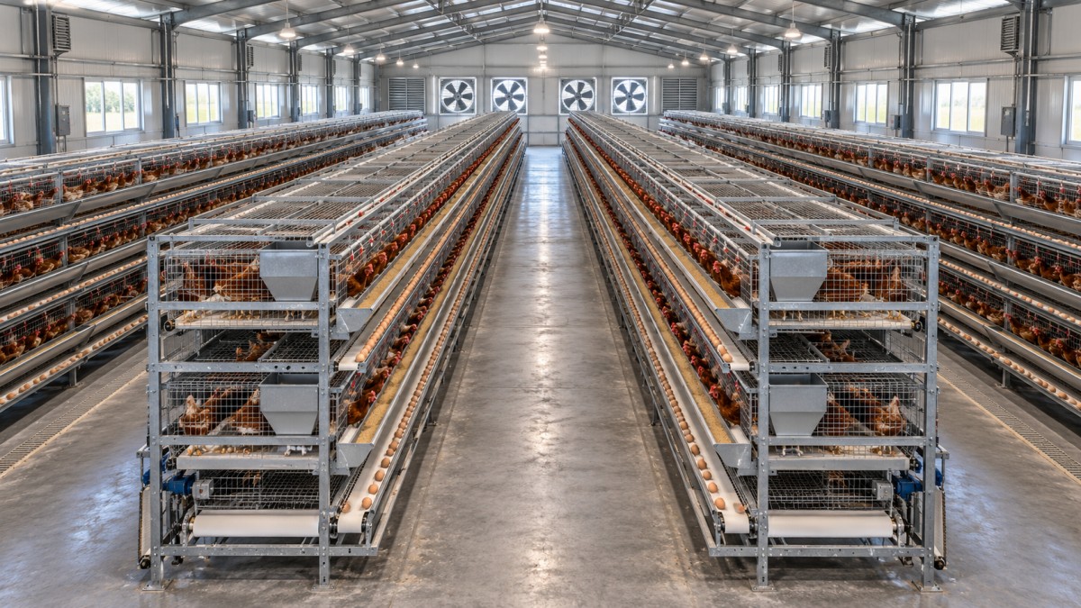
Illustrative calculation—not a product specification: suppose a hypothetical house has an internal length of 60 meters. The proposed layout reserves 6 meters in total for end equipment and cross-access, leaving 54 meters. If a hypothetical cage section repeats every 2.4 meters, 22 complete sections fit, occupying 52.8 meters and leaving 1.2 meters unallocated.
That remainder is not evidence that another section can be added. Nor should it automatically be distributed between access zones. Its location and use must be shown on the layout. The assumed dimensions above explain the calculation only; they are not recommended equipment dimensions or clearance requirements.
Calculate cage capacity separately from house capacity
Once the arrangement is established, calculate the scheduled cage capacity from the actual compartment schedule:
Scheduled birds = rows × sections per row × compartments per section × approved birds per compartment.
This expression works only when the compartment count includes every tier and occupied side of the specified section. Drawings and quotations should state that counting convention explicitly. Otherwise, a project can accidentally multiply by tiers or sides twice, producing an inflated capacity without any obvious error in the arithmetic.
The permitted allocation per compartment requires its own basis. Do not derive it from the building’s gross floor area, and do not accept a nominal “birds per set” figure without knowing what the set contains. Record the usable compartment area, the applicable accommodation requirement and any other constraints governing the bird allocation.
The scheduled cage count is then a candidate house capacity—not the final approved operating capacity. Ventilation, water delivery, feed distribution, manure handling, egg collection and access must each be assessed against that candidate. Where one system supports fewer birds under the design conditions, either reduce the planned flock or redesign the limiting system.
Test the layout under operating and maintenance conditions
Ventilation and the vertical equipment envelope
Adding tiers changes more than the number of compartments. It changes the equipment arrangement within the building and may affect access to upper levels, service routing and the ventilation design. A floor plan should therefore be accompanied by cross-sections showing roof structure, inlets, fans and cage elevations.
The ventilation designer should assess the proposed flock, local design climate, house geometry and selected equipment together. Nominal fan capacity alone does not establish acceptable conditions throughout the occupied zone. Require the design basis to state how equipment resistance, inlet configuration and operating modes have been addressed, with commissioning checks appropriate to the installation.
Egg collection and manure discharge
Trace both systems beyond the last cage section. Egg conveyors need defined transfer points and receiving arrangements. Manure removal needs a workable discharge route and an interface with external handling or storage. Leaving these interfaces outside the cage quotation does not remove them from the building-space requirement.
Check where motors, belt returns, scrapers and transfer assemblies must be reached. A component may fit when installed yet remain difficult to replace. Maintenance access should be demonstrated with the expected task and removal direction, rather than represented by an unexplained blank rectangle.
Feed, water and service access
Confirm how the proposed row length and tier arrangement connect to feed and water distribution. The engineering review should identify supply conditions, isolation points, flushing arrangements and access to components requiring inspection. Where pressure regulation or additional distribution equipment is proposed, include its physical location in the drawing.
Review aisles against real tasks: flock observation, removal of birds, cleaning, fault response and movement of maintenance equipment. A passage that allows a person through may still be unsuitable for the intended work. Applicable fire, building and workplace requirements need separate local verification; equipment spacing should not be presented as proof of safe egress.
Compare alternative layouts on the same design basis
A higher-tier arrangement may offer more cage capacity within the same floor area, but it should not be treated as a free increase in building productivity. Its suitability depends on height, service access, structural interfaces and the supporting systems. A lower arrangement may use more floor space for the same flock while offering a different inspection and maintenance strategy.
Ask bidders to price the same defined scope. Otherwise, a compact cage-only quotation may appear cheaper than an installation that includes access equipment, discharge extensions and service interfaces. Separate equipment purchase cost from installation work, building modifications and the provisions needed to keep the system maintainable.
For expansion projects, show both the initial arrangement and the intended future condition. Empty floor space is not necessarily usable expansion capacity. Future rows may require changes to ventilation, electrical distribution, manure handling or egg collection. Preserve the relevant routes and interfaces only after establishing that the expanded operating condition is feasible.
Use drawing approval and acceptance checks to protect capacity
Capacity should remain provisional until the supplier and project team agree on a coordinated installation package. The following deliverables provide a practical basis for that decision:
- General arrangement: plan and sections showing complete equipment envelopes, access routes, columns and service interfaces.
- Compartment schedule: usable dimensions, compartments per section, occupied sides, tiers and the basis for bird allocation.
- Interface schedule: electrical supplies, water connections, feed entry, egg discharge, manure discharge and external responsibilities.
- Installation requirements: anchoring details, floor tolerances, equipment loads and checks required by the responsible structural designer.
- Acceptance plan: dimensional inspection, functional testing, recorded deficiencies and responsibility for correction.
During installation, verify the first assembled section and a representative row against the approved drawing before repeating errors throughout the house. Record discrepancies in section pitch, alignment, projections and service positions. Changes should pass through drawing control rather than being absorbed informally by narrowing access space.
Before flock placement, reconcile the as-built compartment count with the approved operating capacity and complete the agreed commissioning checks. The project handover should state what was installed, what was verified and which operating limits remain applicable.
The defensible capacity is the bird number supported by the completed housing arrangement and its operating systems—not the largest number obtained from cage dimensions. Keeping those two quantities separate gives project managers a clearer basis for approving layouts, comparing bids and controlling late changes.
Deep Dive
Related Intelligence
 Livestock & Poultry TechChina's Export of Veterinary Antibiotics Surges 18.7% YoY in Q1 2026: Key Industry Impacts and ResponsesAnalyst:Agri-Tech Strategist
 Livestock & Poultry TechChina Feed Industry Association Initiates Revision of Microbial Fermented Feed Additives Group StandardAnalyst:Agri-Tech Strategist
 Livestock & Poultry TechNational Feed Quality Inspection Center Releases Q1 2026 Feed Safety Report: Key Impacts and Industry ResponsesAnalyst:Agri-Tech Strategist