How to size electric motors for pumps
Key Takeaways
- The Kyiv Independent Hit by Suspected Russian CyberattackIT & Security Director
- What is editorial exposure and how does it differ from paid advertising?IT & Security Director
- Apple Warns Users in 99 Countries of Spyware; German Lawmakers' Devices SuspectedIT & Security Director
- How to write technical content for exporters selling machinery abroadChief Civil Engineer
- BW ESS Brings Hams Hall, Europe's Largest Operating Battery Storage Project, OnlineAutomotive Tech Analyst
- How to size electric motors for pumpsChief Civil Engineer
- Trump Administration Pledges $15 Billion in Farm Aid Ahead of Midterm ElectionsAgri-Tech Strategist
- When does automated food processing technology pay for itself?Agri-Tech Strategist
Industry Overview
We do not just publish news; we construct a high-fidelity digital footprint for our partners. By aligning with TNE, enterprises build the essential algorithmic "Trust Signals" required by modern search engines, ensuring they stand out to high-net-worth buyers in an increasingly crowded global digital landscape.
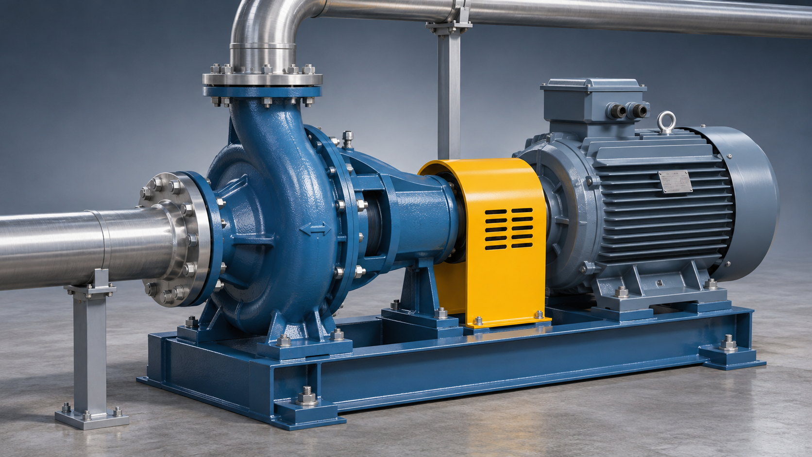
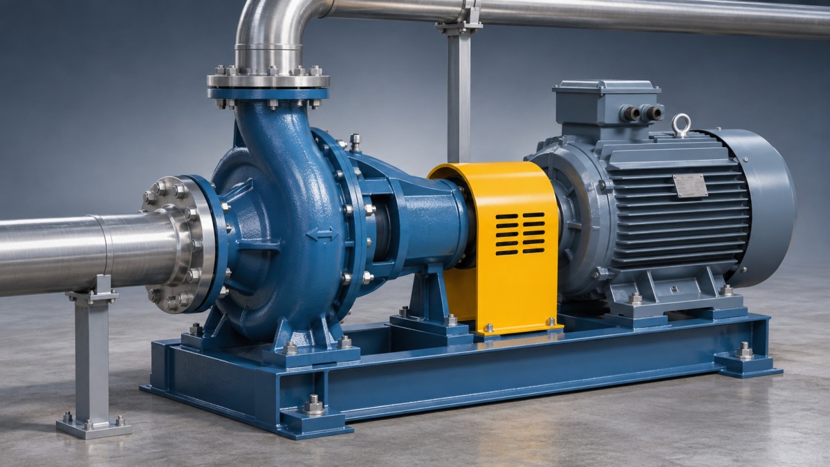
To size electric motors for pumps, calculate the pump’s required shaft power at the most demanding credible operating point, then select a motor with sufficient continuous rated output and starting torque under the actual site conditions. The calculation begins with flow, total dynamic head, fluid density and pump efficiency; it does not end with the power shown at the pump’s duty point.
A motor matched only to a nameplate duty can be overloaded when a centrifugal pump runs at a higher flow than expected, or can fail to accelerate a heavily loaded pump during startup. Conversely, an unnecessarily large motor adds cost and may operate inefficiently at light load. The decision depends on the pump curve, operating range, starting method and motor derating—not on a blanket oversizing rule.
Establish the operating points before calculating power
Start with the required flow rate and total dynamic head (TDH) at each credible operating condition. TDH is the energy per unit weight the pump must add to the liquid. It includes the difference in liquid levels or static pressures between the suction and discharge boundaries, plus friction and other losses through the system. Use a consistent reference for pressure, elevation and velocity; do not add the same pressure or elevation contribution twice.
For a system that draws from one open tank and discharges into another, TDH generally combines the elevation difference between liquid surfaces with pipe, fitting and equipment losses. In a pressurized system, the pressure difference between the boundaries also matters. Friction losses vary with flow, so one calculated head value does not describe the whole operating range.
Identify both normal and limiting conditions: minimum and maximum liquid levels, alternative discharge routes, valve positions, filter fouling and any expected changes in process demand. Check the intersection of each relevant system curve with the pump curve. A low-resistance path can move a centrifugal pump toward higher flow, where its shaft power may exceed the value at the design duty point.
Record the pumped liquid’s density and viscosity at operating temperature. Density directly affects hydraulic power for a given flow and head. Viscosity can also change the pump’s achievable flow, head and efficiency; water-based performance curves may need correction or replacement with manufacturer data for the actual liquid.
Convert hydraulic duty into motor shaft power
In SI units, hydraulic power is calculated as:
Hydraulic power Phyd (kW) = ρ × g × Q × H ÷ 1,000
Here, ρ is liquid density in kg/m³, g is gravitational acceleration in m/s², Q is flow in m³/s, and H is total dynamic head in metres. This is power transferred to the liquid, not the power required at the motor shaft.
Divide hydraulic power by pump efficiency, expressed as a decimal, to estimate pump shaft power. If a gearbox or other transmission sits between motor and pump, divide again by its mechanical efficiency. Use efficiency at the relevant flow and speed rather than the pump’s maximum efficiency unless those points coincide.
Required motor shaft power = Phyd ÷ pump efficiency ÷ transmission efficiency
For example, consider water at an assumed density of 1,000 kg/m³, flowing at 50 m³/h against 40 m of TDH. Converting the flow gives 0.01389 m³/s. Hydraulic power is approximately 5.45 kW. At an assumed pump efficiency of 70%, the pump requires about 7.79 kW at its shaft. With direct coupling and negligible coupling losses, a nominal 7.5 kW motor would already be below that estimate; a larger standard rating would be needed, subject to the operating-range and derating checks below.
These figures illustrate the method, not a recommendation for a particular installation. If the manufacturer supplies a shaft-power curve for the selected impeller, speed and liquid, use that curve to assess the full operating range. Do not divide a published pump shaft-power value by pump efficiency again: that efficiency is already reflected in the shaft-power figure.
Keep electrical input separate
Motor nameplate power normally describes mechanical output at the shaft, not electrical input. To estimate input at a particular load, divide motor shaft output by motor efficiency at that load; include drive losses separately if a variable-frequency drive is used. Motor efficiency therefore matters for energy and supply calculations, but it should not be applied as another divisor when comparing required shaft power directly with the motor’s rated shaft output.
Find the highest credible load, not just the design load
A pump curve usually presents head, efficiency and shaft power against flow. Review the power curve across the range the system can actually reach, including startup, recirculation and abnormal but credible operating states. For many centrifugal pumps, power rises as flow increases; some impeller designs behave differently. The curve for the selected pump is the deciding evidence.
Do not assume that operation near shutoff is automatically safe because flow is low. Even where shaft power is acceptable, prolonged low-flow operation can heat the liquid or damage the pump. Conversely, an unexpectedly open discharge path can move the duty point into a high-flow, high-power region. Minimum continuous flow and maximum allowable operating flow are pump limits as well as motor-sizing inputs.
For positive-displacement pumps, assess power against the highest differential pressure that can occur, including pressure-relief settings and operating transients. Flow may be comparatively insensitive to pressure while torque rises with pressure. A discharge restriction can rapidly overload equipment, so motor selection does not replace correctly designed pressure protection.
Speed changes deserve a separate review. For a given centrifugal pump and comparable fluid conditions, the affinity laws approximate flow as proportional to speed, head to speed squared and power to speed cubed. A modest speed increase can therefore have a large effect on power. Use these relationships for initial estimates, then confirm the manufacturer’s permissible speed and power curves; they are not a substitute for verified data, particularly when efficiency or fluid properties change.
Choose the motor rating with a documented margin
Once the maximum credible shaft demand is known, select a standard motor output that covers it continuously after applicable derating. Add a margin for justified uncertainty, such as incomplete system resistance data, fluid-property variation or future duty already included in the design basis. Avoid stacking several unexplained allowances on top of a conservative pump curve: that can lead to substantial oversizing without addressing the actual uncertainty.
Check which motor conditions differ from the rating basis. High ambient temperature, altitude, restricted ventilation and some drive operating conditions can reduce allowable continuous output. Obtain the motor manufacturer’s derating guidance and compare the derated available output, not merely the nameplate number, with the required power plus the chosen allowance.
A service factor, where stated, is not a substitute for a correctly sized motor. Its permitted use depends on the motor standard, operating conditions and manufacturer’s instructions. Continuous reliance on it can affect temperature rise and expected life. Likewise, the nearest larger rating is not automatically adequate if site derating brings its available output below the calculated demand.
Oversizing has trade-offs. The motor, starter or drive and supply equipment may cost more, and efficiency and power factor can decline at low load. Compare likely operating hours at each load point rather than assuming that the largest motor offers the best reliability or that the smallest acceptable rating always minimises energy use.
Verify starting, acceleration and speed control
A motor with enough steady-state kilowatts can still fail to start the pump. Compare the motor’s available torque throughout acceleration with the pump’s load torque, including breakaway torque, liquid conditions and the inertia of the rotating assembly. The resulting acceleration time must also remain within the motor and starter manufacturer’s limits. Starting against a closed or open valve changes the load profile, so use the procedure specified for the pump.
Supply voltage and starting method affect the available torque. Direct-on-line starting can draw a high current and cause voltage dip; reduced-voltage starters limit current but also reduce starting torque. A soft starter or variable-frequency drive must be selected with enough current and overload capacity for the actual acceleration duty. Confirm voltage dip at the motor terminals, not only the nominal supply voltage.
For variable-speed operation, check the pump load curve against the motor-and-drive torque capability over the entire speed range. A self-ventilated motor may have less cooling at low speed; the acceptable continuous torque depends on the motor design, drive settings and whether independent cooling is provided. At speeds above base speed, available motor torque can fall, while centrifugal pump power demand can rise sharply. Do not assume the drive can deliver rated torque indefinitely at every speed.
Match the mechanical and electrical interfaces
After the power and torque checks, confirm the motor’s rated voltage, frequency, phase, full-load current and speed against the supply and pump selection. Actual induction-motor speed is below synchronous speed at load; use the speed associated with the pump performance data when precision matters. Confirm rotation direction before coupling or commissioning according to the equipment instructions.
Mechanical compatibility includes mounting arrangement, frame, shaft dimensions, coupling or belt loads and alignment requirements. A different frame size may fit the power calculation but not the baseplate or pump assembly. For a vertical pump, verify thrust and bearing arrangements rather than assuming a standard horizontal motor can carry the imposed axial load.
Finally, specify enclosure and cooling arrangements for the environment: moisture, dust, washdown, corrosion and ventilation restrictions can affect suitability. Where the installation involves a hazardous atmosphere, the motor and associated equipment require the appropriate certified construction and installation method for the classified location. Electrical protection settings and cable sizing must be coordinated with the selected motor, drive and applicable installation requirements.
What to request before approving the selection
Keep the design basis alongside the proposed motor datasheet. The pump supplier should provide the selected impeller and speed, head and efficiency curves, and shaft-power curve for the applicable liquid or the corrections used. The motor or drive supplier should confirm continuous output at site conditions, starting capability, acceleration limits and any variable-speed derating.
Resolve any gap between the calculated maximum load and the quoted equipment rating before purchase. In particular, ask whether the pump power curve covers the maximum reachable flow, whether transmission losses are included, and whether the proposed motor can carry the duty after ambient and drive-related adjustments. Those answers make the selection traceable when operating conditions or equipment specifications change.
Deep Dive
Related Intelligence
 Electric MachineryElectric motors rated IP67 — how deep is the water resistance really tested?Analyst:Chief Civil Engineer
 Electric MachineryElectric Motors in Poultry Ventilation Fans — Higher Efficiency, Lower Dust ToleranceAnalyst:Chief Civil Engineer
 Electric MachineryChina’s Green Smart Ship Tech Rules Impact Marine Equipment ExportAnalyst:Chief Civil Engineer